DOI Nr.: https://doi.org/10.25929/276j-2q41
Gerald Fütterer
Technische Hochschule Deggendorf
ABSTRACT
Photonics products often require enhanced optical functionality, which cannot be provided by state of the art optics. This is the case when high-end optical systems as for example holographic 3D displays are developed. Implementation of Bragg diffraction based volume gratings enables small form factor and high definition (HD) natural viewing experience of 3D objects. This is important for modeling 3D data, prototyping, CAD-CAM, computer-integrated manufacturing (CIM), global 3D teleconferencing and mobile infotainment.
For example, holographic 3D displays, which are based on space bandwidth limited wave segment reconstruction, profit from the specific characteristics of thick hologram gratings, which can be referred to as Bragg diffraction based volume gratings. It is explained how to adapt angular, spectral and polarization selectivity in order to provide specific optical functionality, which is mandatory in order to realize HD holographic 3D displays.
A short introduction to backlight units (BLU), complex valued spatial light modulators (C-SLM) and combined field lenses (cFL) of holographic 3D displays is given.
The description of Bragg diffraction based volume gratings is based on the coupled wave theory (CWT). The usage of the 2nd on-Bragg maximum modulation is described. The advantage of the 2nd Bragg diffraction order is explained. Polarization beam splitter (PBS) geometries are described. Specific layouts of holographic 3D displays are explained. BLU and cFL are evaluated. It is shown how the suppression of diffractive crosstalk can be obtained.
Oftmals benötigen neue Produkte der Photonik eine erweiterte optische Funktionalität, die nicht von optischen Standard-Komponenten bereitgestellt werden kann. Dies ist auch für die Entwicklung von holographischen 3D-Displays der Fall. Hierbei ermöglicht die Implementierung von Volumengittern, die auf der Bragg-Beugung basieren, eine kompakte Bauweise und eine natürliche Wahrnehmung von 3D-Objekten in HD-Auflösung. Dies ist für die Modellierung von 3D-Daten, die Erstellung von Prototypen, CAD-CAM, Computer integrierte Fertigung (CIM), weltweit arbeitende Telekonferenz-Systeme und mobiles Infotainment von Bedeutung.
Holographische 3D-Displays, die auf einer, in der Bandbreite limitierten Rekonstruktion von Wellenfrontsegmenten beruhen, profitieren von der spezifischen Charakteristik dicker holographischer Gitter, welche als Bragg-Beugung basierte Volumengitter bezeichnet werden können. Es wird beschrieben, wie die Winkel-, Wellenlängen- und Polarisationsselektivität ausgelegt werden kann, um spezifische optische Funktionalitäten bereitzustellen. Diese sind unter anderem notwendig, um HD-fähige holographische 3D-Displays zu realisieren.
Es wird eine kurze Einführung zu Hintergrundbeleuchtungseinheiten, komplexwertigen räumlichen Modulatoren und kombinierten Feldlinsen von holographischen 3D-Displays gegeben.
Die Beschreibung Bragg-Beugung basierter Volumengitter erfolgt unter Nutzung der CWT (coupled wave theory). Es wird dargelegt, wie das 2-te Maximum der on-Bragg Modulation genutzt werden kann. Der Vorzug der 2-ten Bragg-Beugungsordnung wird erklärt. Polarisations-Strahlteiler-Geometrien werden beschrieben. Spezifische Anordnungen von holographischen 3D-Displays werden erklärt. Beleuchtungseinheiten und kombinierte Feldlinsen werden untersucht. Es wird beschrieben, wie die Unterdrückung diffraktiven Übersprechens erreicht werden kann.
KEYWORDS
Bragg diffraction based volume gratings, holographic 3D displays, multiplex and diffractive cross talk
Bragg-Beugung basierte Volumengitter, holographische 3D-Displays, Multiplex und diffraktives Übersprechen
1. Introduction
The need for realistic 3D data visualization drives the increasing demand for displays which can provide all natural depth cues and thus natural 3D viewing experience. Unfortunately, there is no system on the market which can provide this. For instance, stereoscopic 3D, which is 2x 2D, can provide a limited comfort depth range ΔDz only, which is approximately 15 % of the distance from the user to the display [1]. Furthermore, there are basic physical limits of these 3D display approaches used [2].
Holographic displays - still in the lab - and for example based on space bandwidth limited reconstruction of curved wave front segments, can provide all natural depth cues, a large depth range and a large viewing volume, too. Anyhow, they have not achieved commercial image quality and they are still not commercially available. Several questions may arise. Why does it take that much time? What are the bottlenecks and critical elements of the holographic display technology?
Real-time encoding of 1D-encoded display size spatial bandwidth limited holograms, which means, for example, the implementation of vertical parallax only (VPO), is not an issue any longer. This is done on high-end free programmable logic arrays (FPGA) already. Taking Moore’s law into account, it can be assumed that real-time display size 2D encoding, including iterations for image quality optimization, of spatial bandwidth limited holograms, which means to use 2D-shaped sub-holograms, can be done on FPGA within the next decade. Thus, encoding is not the bottleneck.
Eye tracking of several users, which might, for instance, be based on triangulation, can be provided in real time already. Furthermore, modular arrangements of eye tracking units working in parallel and in a mutually synchronized way can provide enhanced capabilities. Thus, eye tracking is not an issue.
C-SLM dynamically transform the wave field they are illuminated with. Wave fields are generated, which represent the 3D image [2]. Display size C-SLM providing real-time dynamic wave front transformation with a bit depth of at least 8 bit are not available. C-SLM are critical components. Liquid crystal (LC) based diffraction gratings (LCG), which make use of individually controlled electrode lines, can be used to redirect the wave field representing the 3D image to the eyes of the user. For example, the electrode pitch might be ΛE-LCG = 1.6 µm, which means to generate dynamic diffractive phase gratings with a minimum grating period of ΛP-LCG = 3.2 µm. Although display size attenuated phase shifting masks (APSM) had been introduced in high-resolution OLED panel production several years ago, LCG are still critical components. This holds for manufacturing, frame rate and image quality finally obtained. Consequently, it will take a few more years to develop C-SLM and LCG further in order to meet the final product specifications. Anyhow, C-SLM and LCG are not discussed herein in detail.
Holographic displays, which are based on space bandwidth limited reconstruction of curved wave front segments, require partial coherent illumination. This means to provide sufficient collimation and a reasonable large coherence length zc. Both parameters are not an issue in standard display technology.
To use classic display size collimation of wave fields illuminating complex valued spatial light modulators (C-SLM), which provide wave field transformation, will result in bulky display embodiments. Array type collimation units, which might be used in order to reduce the thickness of the backlight unit (BLU), cannot provide high-definition viewing experience (HD), which is related to the angular - best case - resolution of the human eye, which is
1/60 ° deg.
Thick hologram gratings [3], which also can be referred to as Bragg diffraction based volume gratings, are key components, which enable small form factor holographic 3D displays [4, 5]. In this context, small form factor means that a display thickness of less than 0.1 times the display height can be realized. The main point is, that a wave transformation can be realized by using a thin foil only. A maximum efficiency of close to one can be obtained for this transformation, which corresponds to a single propagating diffraction order. Several geometries of reconstruction, which all might have a high diffraction efficiency, can be exposed into a single layer of holographic recording material, which might be, for instance, a photopolymer. Alternatively, several layers containing for example a single geometry of reconstruction only, can be laminated onto each other [6]. Thus, wavelengths and/or beam paths can be separated with high efficiency.
The specific functionality provided by Bragg diffraction based volume gratings is the reason why they are used within illumination units of small form factor holographic 3D display prototypes and as field lenses. Field lenses focus the light, which is modulated by the C-SLM, onto a plane in front of the eye of the user.
The task of the following analysis is to provide a tailored optical design and optimized parameter sets of the Bragg diffraction based volume gratings, which are used within holographic 3D displays, in a way that the diffractive cross talk is minimized.
2. Methodology and Analysis
In this section, a short overview of the methodology used is given. The path through the 3D display’s components is described and analytic methods used are given. The analysis is carried out step by step, starting at the light source and finally reaching the users retina. Boundary conditions and basic assumptions are explained.
2.1 Generic holographic 3D display design, basic functionalities and basic boundary conditions
A generic refractive embodiment of a holographic 3D display is used to explain the function of the backlight unit (BLU), the C-SLM and the field lens (FL). The basic functions of the components can be found in folded diffractive versions of small form factor holographic 3D displays too.
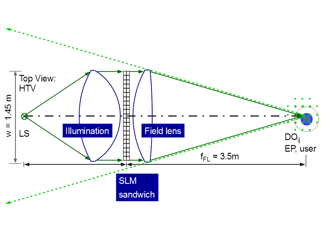
Figure 1: Generic refractive type embodiment of a holographic 3D display based on space bandwidth limited reconstruction of curved wave segments (Top view of a generic embodiment of a 65 inch display diagonal holographic TV, HTV, w: display width, fFL: focal length of the field lens, EP: entrance pupil of the eye of the user, DOij: diffraction orders of the SLM in the EP plane). The dash-dotted black line is the optical axis. The dashed green lines indicate the addressable 3D viewing volume.
Figure 1 depicts a generic enfolded refractive embodiment of a holographic 3D display, which is based on space bandwidth limited reconstruction of curved wave segments. This principle will be explained within this chapter.
The light, which propagates from the light source, which is placed on the left-hand side, is collimated by using a best form lens, which is referred to as collimator or collimation unit. The sandwich type spatial light modulator (SLM) is illuminated with a reasonable plane wave.
In more detail, the angular spectrum of plane waves (ASPW), which has to be provided by the collimation unit, which is referred to as backlight unit (BLU) too, depends on the encoding used.
If 1D encoding and VPO is used, which is sufficient for holographic 3D TV displays, then the vertical ASPW propagating behind the SLM is ΔASPWv ≤ 1/60 ° deg and the horizontal one might be, for instance, within the range of 0.5 ° deg ≤ ΔASPWh ≤ 1 ° deg. Note that the field lens function is superimposed to the VPO encoded lens functions. The circle of least confusion increases if the object point distance to the SLM plane is increased. The resulting astigmatism limits the HD range to approximately one third of the display-to-user-distance. For the generic embodiment being depicted in Figure 1 this limit is approximately 1.2 m in front of the display.
If 2D encoding is used, then the boundary condition to be fulfilled by the BLU is to provide an ASPW of ≤ 1/60 ° deg along the vertical direction and along the horizontal direction. The effect of an increased ASPW are smeared object points and thus a decreased depth range providing HD viewing experience, which is equivalent to the holographic reconstruction of 60 object points per 1 ° deg. It was assumed to limit the parts of 3D images, which are placed in front of the display, to 50 % of the user distance. A reduced ASPW has to be used in order to exceed this range.
It can be assumed that the sandwich type SLM is illuminated with an ASPW being tailored to the requirements of the discrete display embodiment.
The first SLM modulates the amplitude a(x,y,t). This is the A-SLM. The second SLM modulates the phase φ(x,y,t). This is the P-SLM. These two SLM are arranged very close to each other and form the C-SLM. A minimum propagation distance present between the A-SLM and the P-SLM is mandatory in order to reduce the diffractive crosstalk of adjacent C-SLM pixels.
For instance, the smallest clear pixel aperture defines the maximum distance dmaxAP, which might be present between the A-SLM and the P-SLM. Depending on the fill factor (FF) of the SLM pixels, the minimum clear aperture might for instance be 50 % of the SLM pixel pitch ΛSLM. For a holographic 3D TV being placed at a user distance of zuser = 3.5 m, the upper limit of ΛSLM is approximately 100 µm. Note that the SLM’s diffraction pattern is present within the back focal plane of the field lens. This is depicted at the right hand side of Figure 1. The area present between adjacent diffraction orders is the area which can be used for the EP placement. For instance, using the grating equation, a wavelength of λB = 450 nm and a period of ΛSLM = 100 µm results in a diffraction angle of 0.26 ° deg. At a viewing distance of zFL = 3.5 m this results in a distance between the 0th and a 1st diffraction order of 15.75 mm. Taking the intensity distribution of the focal spot of the field lens and further deformations into account, which might be present, a viewing area of 10 mm x 10 mm is practical.
For ΛSLM = 100 µm the clear pixel aperture might for example be 50 µm only. The analysis of internal diffractive SLM sandwich cross talk results in a maximum distance present between the A-SLM and the P-SLM, which is 10x of the minimum clear aperture. For this example, dmaxAP = 0.5 mm only. For this analysis, near field wave propagation was used. This was done by using the software MatLab and the wave propagation module of the software Raytrace. This analysis will not be discussed herein. Consequently, one has to use very thin cover glasses with a thickness of less than 250 µm in combination with a face to face arrangement of the A-SLM and the P-SLM in order to get a C-SLM, which can be used for the holographic 3D TV consumer market.
The complex valued wave field, which is generated by the C-SLM sandwich type, can be described by:
c(x,y,t) = a(x,y,t) × exp(i(φ(x,y,t))) (1)
[2, 7]. This is realized by the C-SLM arrangement described above. Figure 2 depicts a generic visualization of a C-SLM formed by an A-SLM and a P-SLM in series. The first matrix represents amplitude values of the A-SLM and the second matrix represents phase values of the P-SLM. It can be assumed that this complex valued distribution has the size of a very small sub-hologram generating an object point being placed very close to the display plane. Note that the size of 2D sub-holograms, which generate real object points in front of the SLM plane, increases with increased distance present between the object points and the SLM plane. A real object point generated at 50 % of the display-to-user-distance requires an encoding area, which is at least as large as the EP of the user. At 25 %, the sub-hologram might be one third of the EP of the user only. In both cases, HD resolution can be obtained.
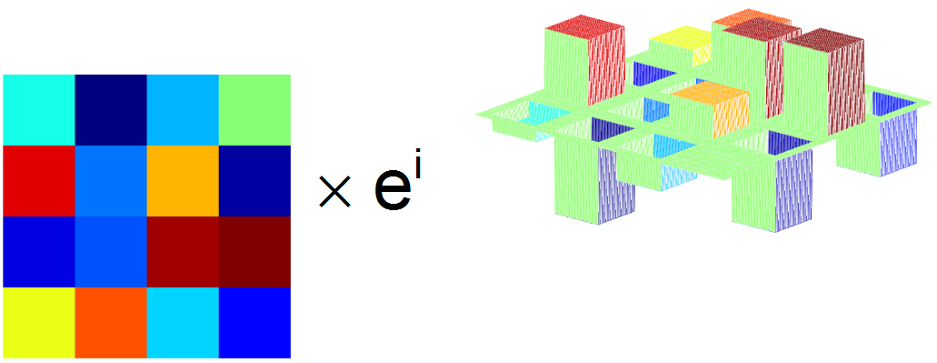
Figure 2: Generic description of the encoding of a complex valued wave field implemented by using a first amplitude modulating SLM (A-SLM) and a second phase modulating SLM (P-SLM) in series.
The complex valued wave field propagating behind the C-SLM represents the 3D scene. For example, single object points are represented by small local Fresnel zone plates generated by the C-SLM. Illuminating the C-SLM will generate object points in space. Depending on the sign of the radius of curvature RSH of the curved wave segment provided by the local sub-hologram (SH), these are real object points in front of the display and imaginary object points behind the display.
Within holographic 3D displays based on space bandwidth limited reconstruction of curved wave segments, the light propagating behind the C-SLM has to be focused onto the user plane. This is done by the so-called field lens (FL). The field lens has a focal length fFL, which is equivalent to the mean average user distance, which is for example fFL = 3.5 m in the case of a holographic 3D TV (see Figure 1).
Within the focal plane of the field lens a diffraction grid type pattern is present, which is defined by the pixel pitch and the primary RGB wavelengths used. The area spanned between the 0th and a 1st vertical diffraction order (1D encoding, VPO) or the area spanned between the 0th, a 1st vertical and a 1st horizontal diffraction order (2D encoding) has to be placed in front of the entrance pupil of the users eye EPuser. This is the window to the pyramid type 3D viewing volume. The red, green and blue viewing windows of the three primary colors (RGB) have to have an overlay error of for example ≤ 1 mm. As it can be seen at the right hand side of Figure 1, the SLM can serve one EP only. In the embodiment discussed herein, both eyes are served time-sequentially. In addition, each color frame is generated time-sequentially. Each eye gets a different view. Thus, a 3D view presented to the user is made of six SLM frames.
Eye tracking has to be used in order to detect the position and the movement of the user eyes.
A so-called tracking unit is required in order to redirect the wave field modulated by the C-SLM to the EPuser. Liquid crystal gratings (LCG) can be used for this [8]. For small movements two LCG, a vertical and a horizontal one, might be used. Within a display product at least three and up to five might be used for this task. Please note that the LCG are also used to correct aberrations, which will be present if diffractive wedge functions are added to a focus function of the field lens. The advantage of an LCG based tracking unit is that it is a thin embodiment already. However, a refractive backlight unit BLU enabling HD resolution is not thin. Furthermore, a refractive field lens (FL) enabling HD resolution is not thin either.
Using Fresnel lenses, surface relief type diffractive optical elements (DOE), as for example Fresnel zone plates or multi order DOE, for the BLU or for the FL is explicitly not an option for HD consumer products. These are prototype solutions only, which generate unacceptable stray light. To be clear, these elements cannot be used as straight forward replacement of refractive or reflective BLU or FL. This is due to the basic physical properties of these optical elements and still holds even in the case of assuming perfect manufacturability. The entire chain of image forming, which also includes the ASPW used for the illumination of the C-SLM, has to be taken into account. Furthermore, multi-order DOE cannot provide the mandatory FL multiplex, which means to multiplex several FL geometries, for example two to seven, for each of the three wavelengths used.
Anyhow, the problem still is that the generic refractive type embodiment of a holographic 3D display based on space bandwidth limited reconstruction of curved wave segments, which is depicted in Figure 1, cannot be used for a mass product. Furthermore, Fresnel lenses or Fresnel zone plates cannot be used either. Thus, a further question may arise. Which type of optical elements can provide the mandatory optical functionality?
Bragg diffraction based volume gratings can provide the optical functionality which is required in order to realize small form factor holographic 3D display products, which are capable of generating HD object point clouds within a large 3D viewing volume. Thus, the problem of small form factor holographic 3D displays can be solved by implementing Bragg diffraction based volume gratings.
2.2. Practicability of Bragg diffraction based volume gratings
A basic boundary condition for the successful implementation of Bragg diffraction based volume gratings (BDVG) into holographic display products is to guarantee the manufacturability. This has to be done in regards to the specifications which have to be fulfilled in order to enable holographic 3D display products. Several aspects have to be taken into account.
Bragg diffraction based volume gratings are exposed into thin films of a recording material by using interference lithography. Based on classic holography, they are capable of transferring a reference wave into a signal wave and vice versa. Multiplex can be implemented within a single foil or within a stacked layer type arrangement. During the exposure or within a post exposure development process, the Bragg planes are generated. The diffraction efficiency η is chosen by generating the appropriate modulation of the refractive index n1. A diffraction efficiency η close to 1 can be obtained. Note that the loss of optical energy, which is due to absorption and scattering, is excluded here. Parasitic diffraction orders can be totally suppressed. Several recording materials might be used, which can be offered in a reasonable price range. The materials can be used on glass or on plastic films as for example on triacetate cellulose (TAC) or other more expensive materials, like for example cyclic polyolefine, showing even better optical quality than TAC, which might be sufficient anyway.
Dichromated gelatin (DCG) requires a wet chemical development. High n1 values of for example 0.1 can be realized with DCG. During the processing of DCG significant thickness variations ΔdHOE might occur. This results in a significant change of the geometry of reconstruction. For plane wave to plane wave geometries, a compensation might be implemented, for instance by changing the initial exposure angles. But the final angular reproducibility is within the 1 ° deg range, which is much too large for the application discussed herein.
Compared to DCG, photopolymers enable reduced angular deviations. The holographic recording film material HRF® (DuPont, Dai Nippon Printing) requires a post exposure bleaching and a post exposure bake at 120 ° C. Depending on the discrete material of the HRF® product family maximum values of n1 of 0.05 or even up to 0.07 (fresh material only) might be realized. The shrinkage is still too large, although the shrinkage is less than the one present for DCG. Even with pre-compensation, the final angular reproducibility is within the 0.5 ° deg range [6], which is still slightly too large for the application discussed herein.
Newer photopolymers Bayfol® HX provided by the company Covestro are based on a matrix approach [9]. A primary polymer matrix provides form stability. The photopolymer system (monomers, oligomers and the photo sensitizer system) is placed within this matrix. Thus, very low post-exposure shrinkage is obtained [10]. The only post-exposure process step is bleaching, which can be implemented by using high power white LED. Depending on the discrete material of the product family maximum values of n1 of up to 0.04 might be realized. An angular reproducibility of < 0.1 ° deg can be obtained. Thus, the reconstruction is very close to the recording. This qualifies Bayfol® HX, for example placed on a TAC substrate carrier film, for the application discussed herein.
A further basic boundary condition for the successful implementation of Bragg diffraction based volume gratings into holographic 3D display products is to guarantee a reasonable low wave front distortion. From a global point of view, the light propagating behind the C-SLM has to be collected within a focal point (ΔxF ≤ ± 0.5 mm). In other words, the FL acts as a global, display size lens. One has to ensure that the spot size of the focus of the FL, which is the zero order spot present in the plane of the EP of the user, does not exceed the 1 mm range. Low shrinkage type photopolymers can provide this. From a local point of view, the wave segment focused onto the retina has to generate a small point spread function (PSF). Aberrations excluded, the PSF is equivalent to the Airy disc [11]. The user should not detect an aberration of the object points. For single Bragg diffraction based volume grating foils, it is sufficient to work with aberrations of up to λ/8 at a 10 mm diameter. For photopolymers showing reasonable low shrinkage the reasonable low wave front aberration of the diffracted light was practically proven. In this context, the aberrations, which are due to thickness variations or stress birefringence of the carrier film, or due to local thickness variations of the photopolymer, have to be taken into account, too. Figure 3 illustrates that Bragg diffraction based volume grating can provide reasonable low wave front distortion, here < λ/60 at a diameter of Ø = 4 mm. For this measurement, a Shack-Hartmann sensor was used. The exit plane of the volume grating was imaged onto the detector plane.
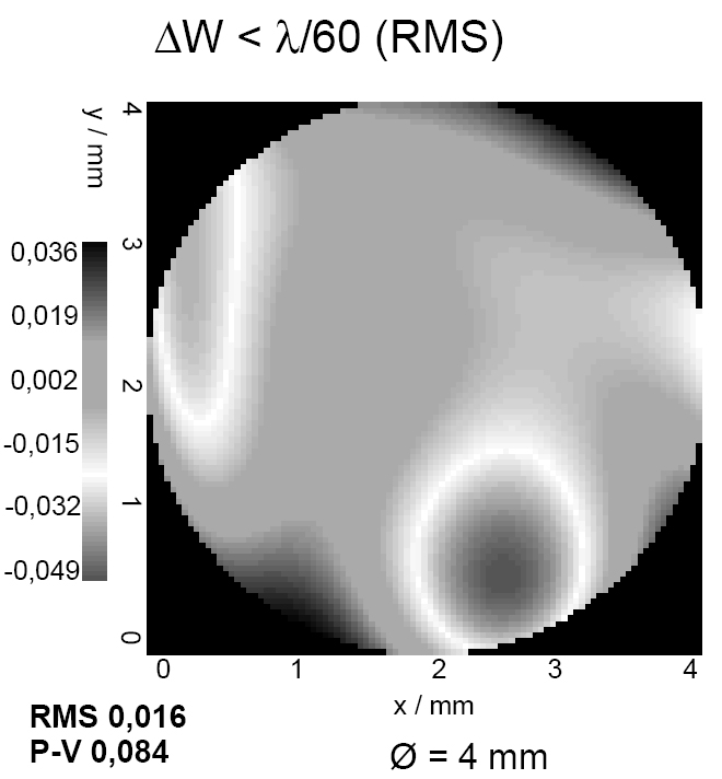
Figure 3: Measured wave front, diffracted by a volume grating (1st Bragg diffraction order [BDO], exit plane imaged onto the detector plane). The aberration is less than λ/60. The measurement area is equivalent to a representative area of the entrance pupil of the human eye EP (dEP = 4 mm).
At this point, it can be concluded that Bragg diffraction based volume gratings can be used within holographic 3D displays, which are based on space bandwidth limited reconstruction of curved wave segment. In other words, this is a realistic candidate, which is not a solitary academic solution only. This means that Bragg diffraction based volume gratings are practically relevant. They are key components, which enable small form factor holographic 3D display products, which can provide HD-3D viewing experience.
2.3. Discrete implementation of Bragg diffraction based volume gratings
The bulky optical elements shown in Figure 1 have to be replaced by Bragg diffraction based volume gratings.
Figure 4 depicts an anamorphic diffractive type wedge BLU, which can be used in front of a C-SLM (in front: in respect to the beam path). The small form factor is obtained by using one dimensional anamorphic beam stretching two times, first along the horizontal direction and afterwards along the vertical direction. Thus, the first grating is a small stripe and the second grating has to have the size of the display.
If the BLU is used at 2x 87.13 ° deg / 0 ° deg (θin / θout), then 20x anamorphic stretching can be obtained. Anamorphic beam - or better wave field - stretching with a factor of 10x to 20x is practical. The anamorphic, diffractive wedge type backlight unit (BLU) can be realized, for instance, in polymethyl methacrylate (PMMA, used as wedge, for example with 20x beam stretching factor) or as air wedge (for example with 10x - 15x beam stretching factor). The air wedge type BLU requires a dielectric multilayer coating optimized for the three primary wavelengths used (RGB, with a reflectivity of R < 5 % being practical at display size and 84.26 ° deg entrance angle). For instance, laser diodes with wavelengths of λB = 450 nm, λG = 520 nm and λR = 640 nm can be used. These wavelengths enable a wide color gamut. The final thickness of the BLU is approximately 1/10x to 1/20x of the display height. Thus, a small form factor BLU can be realized for the illumination of the C-SLM. Behind the BLU a narrow ASPW, which is close to a plane wave, can be assumed.
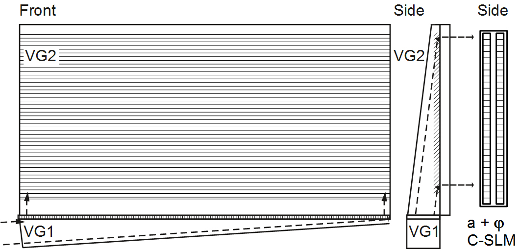
Figure 4: Left and middle: Front and side view of an anamorphic diffractive wedge type BLU. A collimated wave field propagates to a first stripe type volume grating (VG1), which is placed at the bottom. The entrance angle is θin = 84.26 ° deg and the exit angle is θout = 0 ° deg. This results in a 10x stretching factor present along the horizontal direction. The wave field, which is diffracted by the first VG, propagates to the second VG (VG2), which has the size of the holographic display. The entrance angle is θin = 84.26 ° deg. The exit angle, which is the angle the C-SLM is illuminated with, is 0 ° deg. Thus, two times 10x anamorphic stretching is obtained. Right: C-SLM being placed behind the BLU.
The C-SLM generates a spectrum of curved wave field segments, which are equivalent to a 3D cloud of object points. In order to generate the plane of the users viewing window to the 3D scene, which contains the diffraction orders of the C-SLM, a field lens is mandatory. In Figure 1, this is the lens being placed at the right-hand side of the C-SLM. This lens can be replaced by a Bragg diffraction based volume grating. Thus, a small form factor can be obtained. Furthermore, continuous phase profiles, which do not show any phase steps, are present. And last but not least, a multiplex of the geometries of reconstruction of three primary wavelengths and a multiplex of field lens geometries can be realized by using this approach. This enables an increased tracking range. One FL geometry, see for example Figure 5, has to be realized for three wavelengths. In other words, one FL geometry is R-G-B-multiplexed (R: red, G: green, B: blue). Coarse tracking can be combined with fine tracking in order to increase the freedom of movement of the user [8]. Several FL geometries can be multiplexed in order to implement coarse tracking. An important boundary condition, which has to be fulfilled for Bragg diffraction based volume gratings, is to realize a minimum diffraction angle, which is for example
θmin ≥ 10 ° deg (Q factor [3]). Thus, an on-axis lens cannot be realized by using a single Bragg diffraction based volume grating. An on-axis lens can be realized by combining two Bragg diffraction based volume gratings in series. This is referred to as combined field lens (CFL). The on-axis CFL uses a plane-wave-to-plane-wave geometry of reconstruction followed by an off-axis illuminated on-axis focusing lens. This is depicted in Figure 5. Note that the maximum angle, which is realized by the field lens of a desktop type holographic display in air, is, for instance, up to 30 ° deg. Thus, it is sufficient to use an off-axis incident angle of for example
30 ° deg within the photopolymer (still: Q > 10).
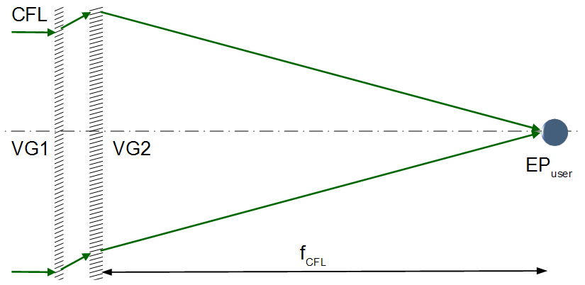
Figure 5: Principle of a combined on-axis field lens (CFL), which is based on two Bragg diffraction based volume gratings VG1 and VG2 in series.
Up to this point, the resulting beam path can be described as: collimated light source ➝ BLU ➝C-SLM ➝CFL ➝ fine tracking (several display size 1D LCG in series) ➝ user being close to the focal plane FCFL of the CFL. In other words, the arrangement depicted in Figure 1 is made slim by using Bragg diffraction based volume gratings, which are tailored to the specific requirements of holographic 3D displays. For further analysis, the specific characteristics of the optical elements used has to be taken into account.
2.4. Angular and spectral selectivity vs. grating parameter
Several geometries of the reconstruction of Bragg diffraction based volume gratings had been taken into account. The specific geometries are results of specific optical designs of small form factor holographic 3D displays.
The calculation of the related diffraction efficiencies and the angular, spectral or polarization dependent change of them is based on the coupled wave theory (CWT) [3].
For the description of the Bragg diffraction based volume gratings, the selectivity of the diffraction efficiency η was analyzed in regards to a change of the entrance angle, the wavelength or the polarization state of light used for the reconstruction. The geometries of reconstruction, which had been used herein, are representative for holographic 3D displays. For instance, the 10x anamorphic air wedge uses a geometry of reconstruction of - 41.55 ° deg / 0 ° deg within the photopolymer, which means within a material that has a refractive index close to n = 1.5.
Figure 6 shows the calculated diffraction efficiency η(ΔθB, n1). Here, ΔθB is the change of the entrance angle the Bragg diffraction volume grating is illuminated with in regards to the so-called on-Bragg angle θB. The value n1 is the modulation of the refractive index of the phase only type of volume grating. The angular range shown is ± 5 ° deg. The modulation of the refractive index goes from zero to 0.04, which is the maximum value for time being Bayfol® HX photopolymers. The geometry of reconstruction within the photopolymer is - 41.55 ° deg / 0 ° deg. The thickness of the recording film is dHOE = 20 µm.
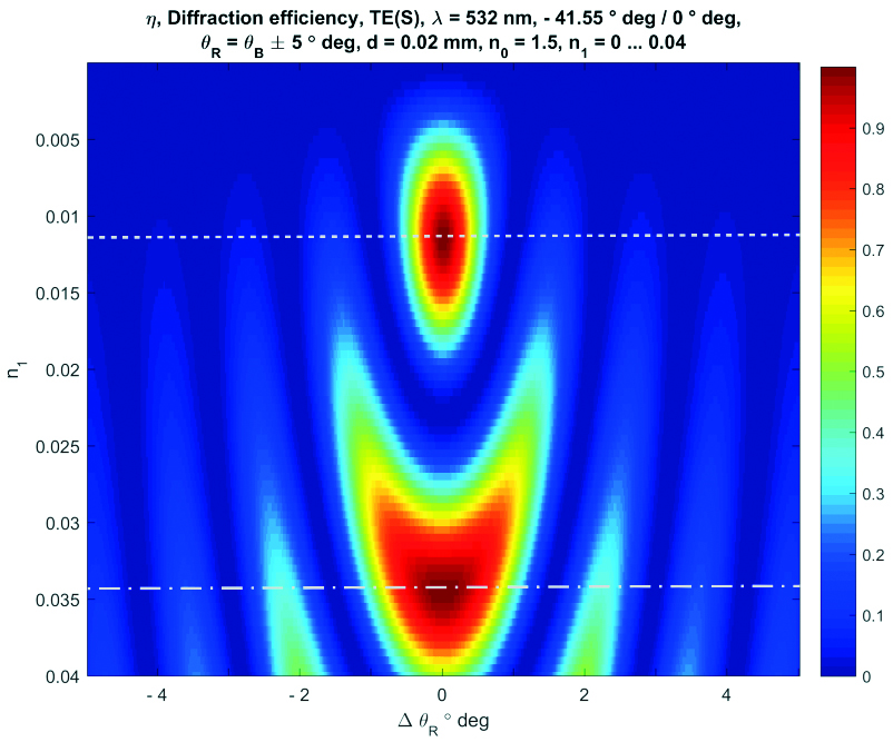
Figure 6: Calculated diffraction efficiency η(ΔθB, n1) for an angular range of 10 ° deg and refractive index modulation n1 of up to 0.04.
The first on-Bragg maximum of the diffraction efficiency η(ΔθB, n1). is obtained at a modulation of n11 = 0.0115 (the 2nd index 1 indicates the 1st on-Bragg maximum of the function shown). This standard exposure state is indicated by a white dotted line. In other words, the standard situation is to realize an index modulation of n11 = 0.0115 for the related geometry and the related grating thickness. Slightly over modulating decreases the diffraction efficiency. Higher index modulation can be used to realize the 2nd on-Bragg maximum of the diffraction efficiency η(ΔθB, n1).
The second on-Bragg maximum of the diffraction efficiency η(ΔθB, n1) is obtained at a modulation of n12 = 0.0345 (the 2nd index 2 indicates the 2nd on-Bragg maximum of the function). This exposure state is indicated by a white dash-dot line.
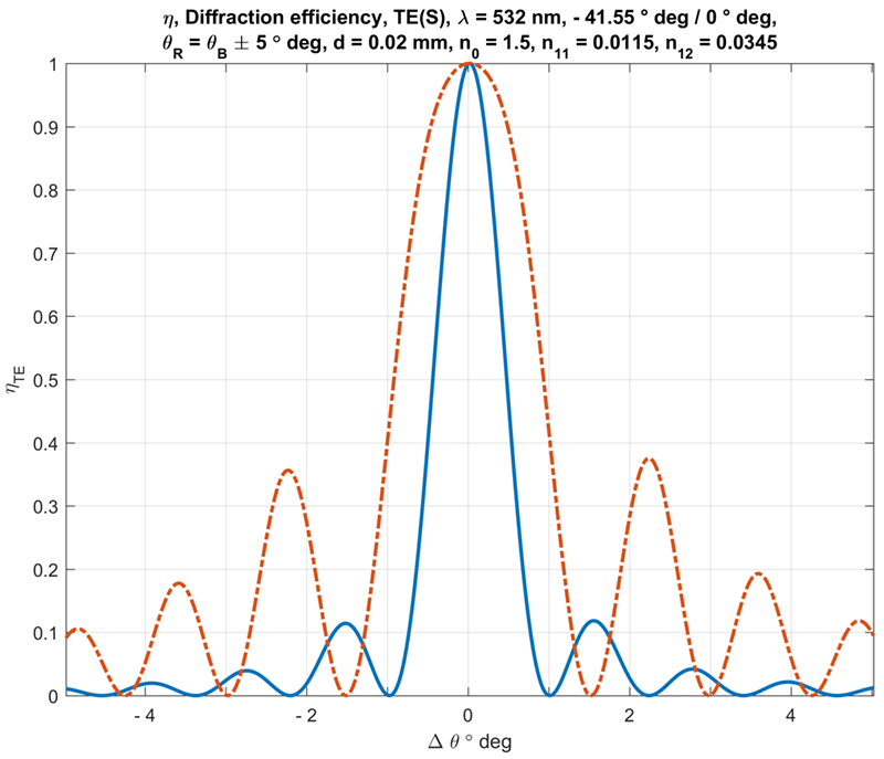
Figure 7: Calculated angular selectivity of the 1st (solid blue line) and the 2nd (red dash-dot line) maximum of the diffraction efficiency η(ΔθB, n1).
Figure 7 shows the calculated angular selectivity of the 1st and the 2nd maximum of the diffraction efficiency η(ΔθB, n1). The curves are cross sections of the function shown in Figure 6.
The point here is that the central angular range enabling diffraction efficiency η(ΔθB) ≥ 0.95 is increased by a factor of 2.5 for the second on-Bragg maximum. This is of importance in the case of combining several Bragg diffraction based volume gratings together. On the one hand this means to be able to work with relaxed alignment tolerances, but on the other hand increased side lobes have to be taken into account. The analysis of the system described herein shows that this type of over modulation is not practical for the proposed system. As a result, the 1st on-Bragg maximum of the diffraction efficiency η(ΔθB, n1) has to be used. The geometries of reconstructions have to be optimized in regards to this fist maximum.
Figure 8 shows the calculated diffraction efficiency η(ΔθB, n1). Here, ΔθB is the change of the entrance angle in regards to the on-Bragg angle θB. The value Δλ is the change of the wavelength used for reconstruction. The geometry of reconstruction within the photopolymer is - 41.55 ° deg / 0 ° deg (BLU). The thickness of the recording film is
dHOE = 20 µm. The central wavelength is λ = 532 nm. The entire wavelength range used is ± 100 nm. Thus, the blue and the red spectral range can be found at the upper and at the lower rim respectively.
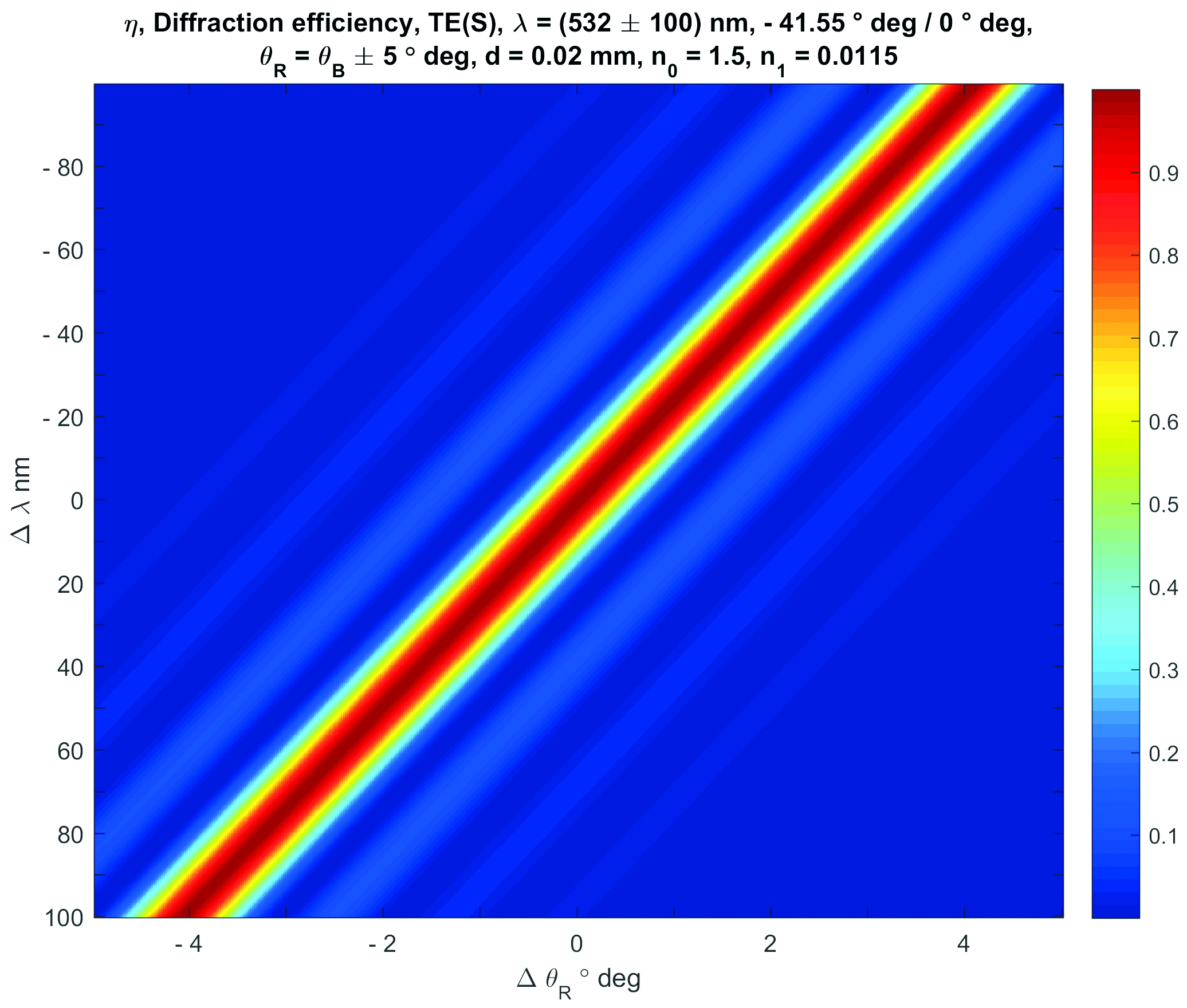
Figure 8: Calculated diffraction efficiency η(ΔθB, Δλ) of a Bragg diffraction based volume grating designed for a λ = 532 nm BLU geometry.
In Figure 8, it can be seen that the green grating still shows very small ± 3rd side lobes, which are within the angular range of blue and red light. This holds if identical entrance angles are assumed, which might be realistic in the case of a wedge type BLU.
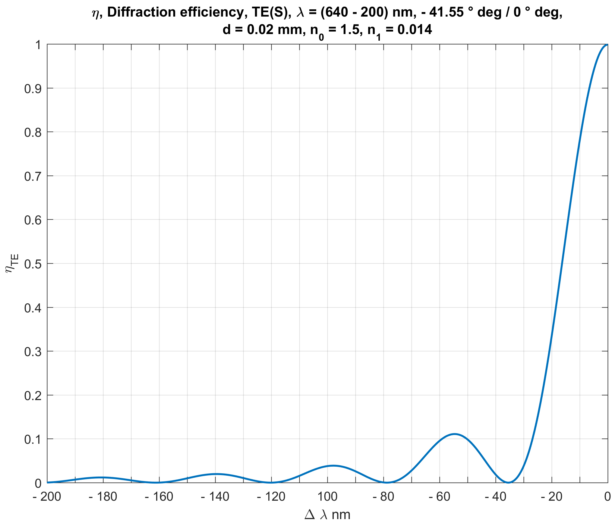
Figure 9: Calculated diffraction efficiency η(Δλ) of a Bragg diffraction based volume grating designed for a λ = 640 nm BLU geometry at on-Bragg illumination.
Figure 9 shows the calculated diffraction efficiency η(Δλ) for a λ = 640 nm BLU geometry at ΔθB= 0 ° deg. The wavelength spans the range from λmax = 640 nm to λmin = 440 nm. Comparing Figure 9 with Figure 8 shows that diffractive crosstalk will be present in the case of multiplexing both geometries. The intensity of red light, which will of course be diffracted in a parasitic direction by the grating designed for 532 nm wavelength, is within the < 5 % range. The intensity of blue light, which will be diffracted in a parasitic direction by the grating designed for 640 nm wavelength, is within the < 2 % range. If the light does not propagate to the viewing zone of the user space, which is the case for the chosen geometry of diffraction, then it is just an acceptable loss of energy. The anamorphic BLU geometry is based on a plane-wave-to-plane-wave transformation. Thus, the intensity taken out of the beam path by the diffractive crosstalk is constant within the display plane.
The analysis shows that several options can be used in order to eliminate the diffractive cross talk within a wedge type BLU. The direct approach is to increase the grating thickness, for instance to a value of dHOE = 30 µm. For this approach, the practical thickness limit is dHOE = 40 µm. Figure 10 shows the calculated diffraction efficiency η(ΔθB, Δλ). The geometry of reconstruction within the photopolymer is - 41.55 ° deg / 0 ° deg (BLU, air wedge, 10x). The thickness of the recording film is increased to the upper practical limit of dHOE = 40 µm. The central wavelength is λ = 520 nm, which enables a wide color gamut. The entire wavelength range used is ± 100 nm. The drawback of the increased thickness approach, which provides a much more narrow selectivity of the BLU gratings, is a much tighter alignment tolerance.
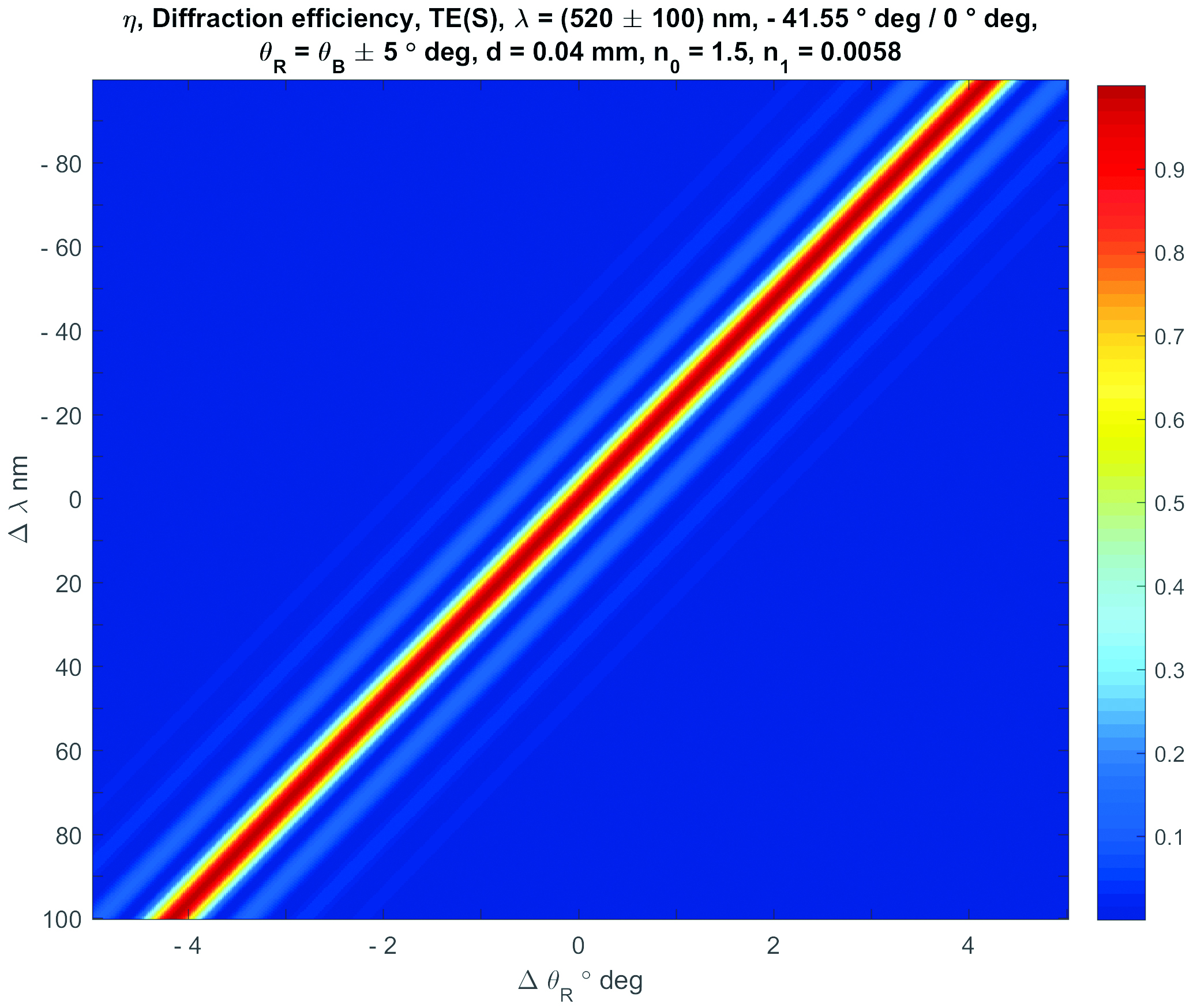
Figure 10: Calculated diffraction efficiency η(ΔθB, Δλ)of a Bragg diffraction based volume grating designed for a λ = 520 nm anamorphic BLU geometry (10x in air).
Another approach is to use an anamorphic BLU geometry of - 41.55 ° deg / 0 ° deg for λB = 450 nm and for λR = 640 nm, while using a BLU geometry of + 41.55 ° deg / 0 ° deg e.g. for
λG = 520 nm. This means to flip the entrance angle of the green light.
To use λG = 520 nm instead of λG = 532 nm results in a wider color gamut. Reasons to use diode pumped solid state (DPSS) lasers working, for instance, at λG = 532 nm instead are the high optical power, the small line width, the small spectral drift and the high stability of the output intensity. However, a display product has to realize a wide color gamut. Thus, green lasers which meet all requirements have to be developed.
To use special, slightly changed wavelengths which are placed in the local minima of adjacent side lobes is not an option. The reversed way is more realistic: first define and fix the wavelengths, for instance to 450 nm, 520 nm and 640 nm and afterwards slightly change the geometries of reconstruction of the Bragg diffraction based volume gratings in order to get into the local minima of adjacent selectivity curves. For this, the angles and/or the layer thickness can be changed.
A further boundary condition is that 1D encoding uses a so-called incoherent direction. For VPO, this is the horizontal one. The ASPW along this direction is for example (0.5 to 1) ° deg. Furthermore, the coherent wave field modulated by the C-SLM has to be accepted by the Bragg diffraction based volume gratings within a reasonable wide angular range. This range is, for instance, ≥ ± 0.5 ° deg. In other words, the angular acceptance along the coherent direction has to be e.g. ≥ ± 0.5 ° deg. Gratings used behind the C-SLM of a 2D-encoded holographic 3D display have to accept ≥ ± 0.5 ° deg with reasonable high diffraction efficiency η, which is e.g. η ≥ 0.75, along the vertical and along the horizontal direction. For example, cutting out the small angular range of the user’s viewing window to the 3D scene, which is the range between the 0th and a 1st diffraction order of the C-SLM grid, does explicitly not avoid higher diffraction orders in the focal plane of the CFL, which is the far field of the C-SLM, which contains the complex values representing 3D objects. To cut all higher orders off like this results in a huge loss of light. In the far field, the diffraction orders will be generated again. The practical approach to the suppression of higher diffraction orders is to use C-SLM pixel apodization like the well-known Gauss or Kaiser-Bessel windows and a reasonable wide angular acceptance angle of the Bragg diffraction based volume gratings.
2.5. Polarization selectivity vs. grating parameter
Another way which can be used in order to reduce diffractive cross talk is to take the polarization dependence of the diffraction efficiency η into account. Starting from the CWT [3], it can be shown [12] that the following equation holds for large angles of diffraction:
νTM = νTE cos(θ), ηTM = sin2(νTE cos(θ));
with ν = dHOEn1/(λ√(crcs)). (2)
The grating parameter ν contains the thickness dHOE of the Bragg diffraction based volume grating, the modulation of its refractive index n1, the wavelength λ and the direction cosine of the reference and the signal beam cr, cs. Generalizing equation (2) and taking the separation of different polarization states into account leads to a set of polarizing beam splitter (PBS) geometries. This includes a 90 ° deg PBS geometry and a 60 ° deg PBS geometry, which can be used for beam combiner based C-SLM, which combine two adjacent phase pixels, which might be practical for ≥ 100 µm pixel pitch only. A diffraction efficiency of ηTE > 0.98 and ηTE/ηTM > 200 can be realized by using the first and the second Bragg diffraction order [6]. The second Bragg diffraction order has the advantage of using for example Λ2= 600 nm grating period instead of Λ1= 300 nm. This can be used to avoid decreased diffraction efficiencies which are due to a resolution limit of the material. Furthermore, relaxed exposure and measurement conditions can be obtained for total internal reflection (TIR) or close to TIR geometries.
Figure 11 shows the measured angular selectivity of a Bragg diffraction based volume grating PBS illuminated with TE and TM polarized light, which is optimized for the 2nd Bragg diffraction order.
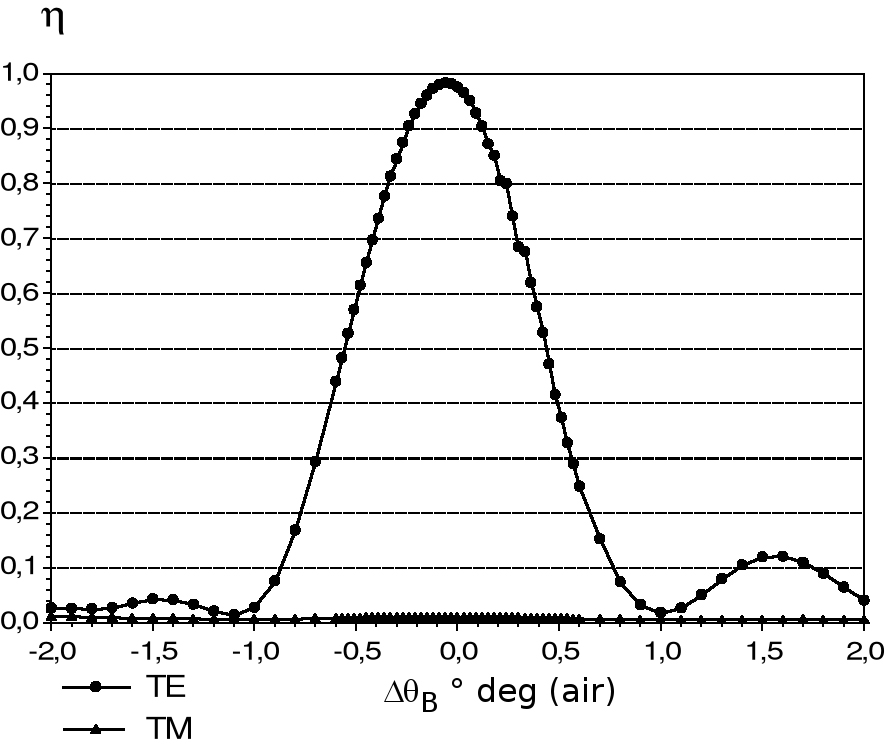
Figure 11: Measured angular selectivity of a Bragg diffraction based volume grating PBS illuminated with TE and TM polarized light. The diffraction efficiency is optimized for the second Bragg diffraction order (2nd BDO, η(Δθ) in air). The grating period is Λ2= 600 nm, the diffraction angle is 90 ° deg within n = 1.5. The design wavelength and the wavelength used for reconstruction is λR = 650 nm.
A further analysis of equation (2) shows that there is a PBS geometry at - 41.41 ° deg / 0 ° deg, which is very close to the geometry of the 10x anamorphic air wedge BLU, which is - 41.55 ° deg / 0 ° deg. This implies to use a PBS geometry within the BLU, for instance for λ = 520 nm. A drawback of this approach might be the use of an additional multi-order retardation foil, which has to change the polarization state of the light if required. If C-SLM are used, which have color filters and patterned retarders for RGB, then this might be practicable. Using polarization selectivity for diffractive crosstalk reduction is an option. But it is not the preferred one.
2.6. Crosstalk within display size combined field lenses
The simulation of different geometries of reconstruction of display size components, which are characterized by a spatial variation of the local diffraction angle of Bragg diffraction based volume gratings, was carried out by using the optical design software Raytrace. This special optical design software was developed at the Chair for Optics of the University of Erlangen-Nuremberg.
Figure 12 is a central projection view of 3D ray tracing. A holographic desktop display with a focal length of fcFL = 600 mm and an on-axis focus was assumed. The combined field lens used for this simulation is designed for 520 nm, but illuminated with all three display wavelengths. For this combined field lens, a first single grating was implemented, which diffracts all three wavelengths (see VG1 in Figure 5). This might for instance be a surface relief grating or a switchable LC grating. That is why the off-axis field lens designed for 520 nm wavelength is illuminated with RGB-angles, which are defined by the diffractive dispersion of the first thin grating. Thus, the parasitic colors generate deformed parasitic on-axis foci. Although the cross talk is low, the parasitic light will be focused within the user space. The analysis of the intensities shows that the foci are not that critical. There is other “on-axis” user at these positions. In this example, the green grating causes a large crosstalk and takes out light used for the blue and the red reconstruction. Thus, the simulation shows significant local intensity variations in the blue and in the red illumination planes. Intensity values within the range of 10 % of Imean can be compensated by using a look up table (LUT). The local values of the LUT can be used as compensation values for the encoding of the local sub-holograms.
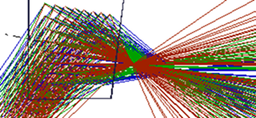
Figure 12: Raytracing of an off-axis Bragg diffraction based volume grating field lens, which is designed for λG = 520 nm. The lens is illuminated with λG = 520 nm, λB= 450 nm and λR = 640 nm wavelength. Collimated light enters the green off-axis field lens (comparable to VG2 in Figure 5) from the lower left-hand side. The lens is illuminated off-axis and forms an on-axis focus. The colors of the rays are equivalent to the wavelengths used.
An arrangement using propagation of RGB light at dispersion angles, which can be seen in Figure 12, is not preferable. This is due to the generation of significant parasitic diffractive crosstalk and intensity inhomogeneity. Thus, it is preferred to implement larger angles for shorter wavelengths and vice versa. This can be referred to as the implementation of reversed dispersion angles.
In order to provide a reasonable tracking range for the user, several field lenses have to be multiplexed for each color. It is preferred to use an LCG behind the C-SLM, which is only used for discrete angular switching. This is required to address a set of multiplexed field lens geometries. This can be referred to as controllable coarse tracking. Behind the stack of multiplexed combined field lenses a stack of polarization type LCG can be placed, which provides the fine tracking.
An embodiment with reduced complexity might use two switchable off-axis field lenses for each color. The horizontal off-axis angle might for instance be ± 10 ° deg. This means to use six multiplexed combined field lenses in total. Twelve Bragg diffraction based volume gratings are used for this (mind the CFL). This points out that low cross talk, low scatter and low absorption are important parameters.
Figure 13 shows a top view of a Bragg diffraction based volume grating lens designed for 640 nm wavelength and a 10 ° deg off-axis focus. The focal plane is placed 600 mm in front of a holographic display. The lens is illuminated with λG = 520 nm, λB = 450 nm and λR = 640 nm wavelength. The three wavelengths propagate at reverse diffractive dispersion. Here 20 ° deg is used for red, 30 ° deg for green and 40 ° deg for blue light. The ray trace analysis of the Bragg diffraction based combined field lenses has shown that this minimizes the diffractive cross talk.
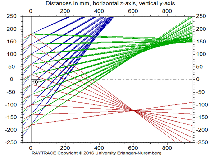
Figure 13: Top view of a Bragg diffraction based volume grating lens designed for λR = 640 nm and 10 ° deg off-axis focus. The focal distance is 600 mm. The lens is illuminated off-axis with λG = 520 nm, λB= 450 nm and λR = 640 nm. Illumination angles, which are reverse to diffractive dispersion, are used. The colors of the rays are equivalent to the wavelengths used.
Figure 14 shows the simulated distribution of the green (λG= 520 nm) intensity component of reconstruction at the exit plane of the red (λR= 640 nm) off-axis field lens. This field lens is the one shown in Figure 13. The maximum diffractive cross talk of the green light is 3.49 %. This is a reasonable low value. Note that there is no critical focus region formed and no zone of increased parasitic green intensity, which might disturb other users placed in the viewing range of the display.
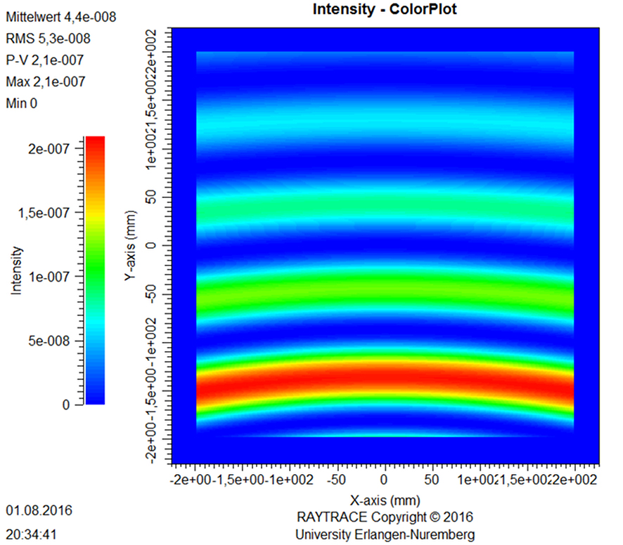
Figure 14: Distribution of the green (λG= 520 nm) component of reconstruction at the exit plane of the red (λR= 640 nm) off-axis field lens (see Figure 13). The lower part represents the left display side.
Due to the fact that the distribution shown in Figure 14 is stable, it can be directly implemented into a correction value type LUT. Thus, the results of simulations or even measurements (calibrations) can be used to correct the sub-holograms during the process of hologram encoding. In other words, one can take a realistic distribution of the illumination into account and thus increase the image quality of a holographic 3D display finally obtained.
Figure 15 shows the simulated distribution of the blue (λG= 450 nm) intensity component of reconstruction at the exit plane of the red (λR= 640 nm) off-axis field lens. This field lens is the one shown in Figure 13. The maximum diffractive cross talk of the blue light is 1.6 %. This is a reasonable low value. As it can be seen in Figure 13, there is no critical focus region formed which might disturb other users.
The question may arise how to interpret the distribution of the efficiency of the parasitic diffractive cross talk which can be seen in the Figures 14 and 15. This can be compared to Figure 8, which shows the calculated diffraction efficiency in the case of varying the design entrance angle and the design wavelength used for reconstruction. Note the side lobes. The simulations shown in Figures 14 and 15 are based on fixed entrance angles being not the design entrance angles and on fixed wavelengths, which are not the design wavelengths either. Here, the local geometry of reconstruction is changed. Thus, side lobes of the diffraction efficiency can be seen. Furthermore, this is done in two dimensions, which is due to the field lens function. Thus, the parasitic cross diffraction type side lobes are curved. See also Figure 13 for orientation and note that this is a top view.
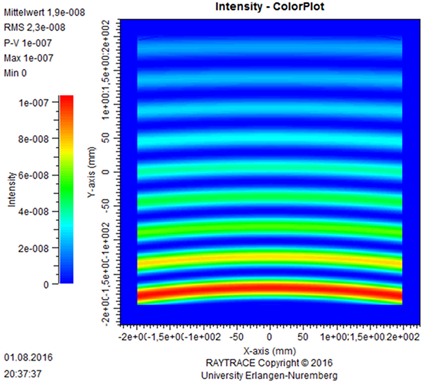
Figure 15: Distribution of the blue (λB= 450 nm) component of reconstruction at the exit plane of the red (λR= 640 nm) off-axis field lens (see Figure 13). The lower part represents the left display side.
The counter diffraction dispersive propagation of the wave fields of the different primary colors is a preferable approach in order to suppress the diffractive crosstalk within holographic 3D displays.
3. Results
The parameter space of Bragg diffraction based volume gratings provides reasonable high flexibility which can be used for the implementation of these gratings within holographic 3D displays.
The small form factor provided is practical for holographic 3D display product solutions.
The performance parameters of new photopolymers are sufficient for holographic 3D display product solutions, too.
The multiplex capabilities of Bragg diffraction based volume gratings can be used to realize the required beam paths for the primary display colors.
For coarse tracking, several geometries of reconstruction can be implemented for each primary color. Thus, it is practical to multiplex field lens functions.
The diffractive cross talk is a boundary condition, which has to be taken into account. The simulations had shown that film thickness and geometry variations can provide sufficient cross talk reduction.
In addition to this, the option of partial beam path flipping was evaluated. Thus, the mutual overlap of side lobes of the spectral and/or angular selectivity curves of different diffractive geometries of reconstruction could be minimized.
The distribution of the diffractive cross talk is homogeneous for BLU geometries which are based on plane-wave-to-plane-wave transformations.
Combined field lens geometries could be optimized in a way to realize reasonable low diffractive cross talk. Residual intensity variations can be compensated by using a LUT. The values stored in a LUT are used in order to correct the encoding of the sub-holograms. Calibration data can increase the holographic 3D image quality finally obtained.
By using simulations, it has been shown that the diffractive crosstalk can be reduced to a practical level. Anyhow, further development has to be done within the next decades.
4. Conclusion
Bragg diffraction based volume gratings can be used within small form factor holographic 3D displays which are based on space bandwidth limited reconstruction of curved wave field segments. They can be used within anamorphic backlight units (BLU) providing, for example, up to 20x beam stretching. These types of diffractive BLU can provide collimated illumination of the C-SLM plane.
Bragg diffraction based volume gratings can be used in order to realize multiplexing of combined field lenses. The diffractive cross talk can be kept reasonable low. Although the manufacturing of large scale volume gratings which show small angular variations will be challenging, this initial cross talk study has pointed out that Bragg diffraction based volume gratings will be key components within small form factor holographic 3D displays which are based on space bandwidth limited reconstruction of curved wave field segments.
5. Outlook
Further optimization of the geometries of reconstruction, which are present within small form factor holographic 3D displays, can be carried out. This might also include slight shifts of for example the three primary RGB wavelengths λ01, λ02 and λ03 used (but still at high color gamut). An angular flip, which might be used in order to minimize the diffractive cross talk, can, for instance, be carried out as up-down and as left-right operation. In other words, there are still additional options which can be used for cross talk reduction. Furthermore, longitudinal apodized volume gratings, which do not have diffractive side lobes at all, can be realized. This approach was theoretically confirmed by using Maxwell solver based simulations and it was practically confirmed by realizing tailored exposures [4]. This approach provides much denser multiplex operations than standard Bragg diffraction based volume gratings. This is important for providing a wide tracking range. However, much development has to be done in order to make display size longitudinal apodized volume gratings standard items.
6. Acknowledgement
The author would like to thank Prof. Dr. Norbert Lindlein of the Chair for Optics at the University of Erlangen-Nuremberg for providing the optical design software Raytrace, which is capable of analyzing the optical functionality of Bragg diffraction based volume gratings being integrated in classical optical systems.
7. Disclosure policy
The author declares that he has no financial interests with regards to this publication and that there are no conflicts of interests which might be related to this publication.
8. References
[1] Choi, Hee-Jin; Kim, Joo-Hwan; Park, Jae-Byung; Lee, Byoung-Ho (2007): “Analysis on the Optimized Depth of 3D Displays Without an Accommodation Error.” In: The 7th International Meeting on Information Display (IMID 2007), Daegu, Korea; Paper 56-4, pp. 1811–1814.
[2] Poon, Ting-Chung (2006): Digital Holography and Three-dimensional Display. Principles and Applications. New York, London: Springer Science+Business Media Inc.
[3] Kogelnik, Herwig (1969): “Coupled Wave Theory for Thick Hologram Gratings.” In: Bell System Technical Journal 48 (November), pp. 2909–2947.
[4] Fütterer, Gerald (2010): Compact Holographic Display Product Solutions. Invited Talk at the International Workshop on Holographic Memories and Display (IWHM&D). Tokyo, Japan, November 15–16, 2010.
[5] Fütterer, Gerald; Leister, N.; Haussler, R.; Reichelt, S.; Erler, C. (2011): Small Form Factor for Holographic 3D Display Product. Paper presented to 2011 Collaborative Conference on 3D & Materials Research (3DMR). Jeju City, South Korea, June 2011.
[6] Fütterer, Gerald: Holographisch optische Module in Photopolymer für DVD-Abtastsysteme. Diplomarbeit. Universität Erlangen-Nürnberg, Mai 1998. Lehrstuhl für Optik/Physikalisches Institut.
[7] Born, Max; Wolf, Emil (1991): Principles of Optics. Oxford: Pergamon Press.
[8] McManamon, Paul F.; Bos, Philipp J.; Escuti, Michael J.; Heikenfeld, Jason; Serati, Steve; Xie, Huikai; Watson, Edward A. (2009): “A Review of Phased Array Steering for Narrow-Band Electrooptical Systems. Rapid, Accurate, Non-mechanical Techniques for Steering Optical Beams Can Provide the Kind of Efficient Random Access Pointing Offered by Microwave Radars.” In: Proceedings of the IEEE 1997,No. 6 (June), Vol. 97), pp. 1078–1096.
[9] Bruder, Friedrich-Karl; Deuber, François; Fäcke, Thomas; Hagen, Rainer; Hönel, Dennis; Jurbergs, David; Rölle, Thomas; Weiser, Marc-Stephan (2010): “Reaction-diffusion Model Applied to High Resolution Bayfol HX Photopolymer.” In: Hans I. Bjelkhagen and Raymond K. Kostuk (Eds.): Proceedings of SPIE 7619. Practical Holography XXIV: Materials and Applications, pp. 761901I.
[10] Berneth, Horst; Bruder, Friedrich-Karl; Fäcke, Thomas; Jurbergs, David; Hagen, Rainer; Hönel, Dennis; Rölle, Thomas; Walze, Günther (2014): Bayfol HX Photopolymer for Full-color Transmission Volume Bragg Gratings. In: Hans I. Bjelkhagen and Michael V. Bove (Eds.): Proceedings of SPIE Vol. 9006. Practical Holography XXVIII: Materials and Applications, pp. 900602-10.
[11] Goodman, Joseph W. (1968): Introduction to Fourier Optics. New York: McGraw-Hill Book Company.
[12] Kobolla, Harald (1995): Holographische Komponenten für optoelektronische Datenvermittlungssysteme. Dissertation. Universität Erlangen-Nürnberg. Lehrstuhl für Optik/Physikalisches Institut.

Prof. Dr. Gerald Fütterer
Prof. Dr. Gerald Fütterer studierte Physik an der Technischen Universität Dresden und der Friedrich-Alexander-Universität Erlangen-Nürnberg (FAU). Er promovierte über Interferenzlithographie bei λ= 157 nm und Interferometrie bei λ= 193 nm zur Messung von lithographischen Phase Shift Masken (PSM). Von 2004 an arbeitete er 3 Jahre lang an der Physikalisch-Technischen Bundesanstalt (PTB) in der Arbeitsgruppe Winkelmesstechnik der Abteilung 5: Fertigungsmesstechnik. Ein Schwerpunkt lag auf der Entwicklung optischer Messtechnik. Er führte PSM in Autokollimationsfernrohren (AKF) ein.
Nach Abwerbung durch die SeeReal Technologies GmbH in Dresden arbeitete er 9 Jahre lang an der Entwicklung holographischer 3D Displays. Er führte Bragg-Beugung basierte Volumengitter in holographische 3D Displays ein, baute interferenzlithographische Belichtungslabore auf (Master- und Kopier-Labor) und etablierte die Verarbeitung dieser speziellen Gitter. Ende 2008 wurde ihm die Position des ,,Head technology & Research‘‘ angeboten, Ende 2011 dann die Position des Wissenschaftlichen Leiters (engl.: Chief Scientific Officer (CSO)). Er war maßgeblich an der Entwicklung holographischer 3D Displays beteiligt und als CSO für diese verantwortlich. Seit 2016 ist er Professor für Produktionstechnik, Messtechnik, Berechnung optischer Systeme & Komponenten an der Technischen Hochschule Deggendorf.
Prof. Dr. Gerald Fütterer studied physics at Technical University Dresden and at Friedrich-Alexander-University Erlangen-Nuremberg (FAU). His dissertation was about interference lithography at λ = 157 nm and interferometry at λ = 193 nm being used for the measurement of lithographic phase shift masks (PSM).
From 2004 onwards, and for three years, he worked at the Physikalisch-Technische Bundesanstalt (PTB, German NIST equivalent) in Brunswick within the working group of angular metrology, which is a part of the Division 5, Precision Engineering. He developed optical measurement systems and introduced PSM into autocollimators (AC).
After being poached by the SeeReal Technologies GmbH in Dresden, he developed holographic 3D displays for nine years. He successfully introduced Bragg diffraction based volume gratings into holographic displays and established processing of photopolymers by installing a master and a copy lab. In 2008, he was offered the position of Head technology & Research and in 2011 the position of Chief Scientific Officer (CSO). While serving as CSO, he led and was responsible for the development of holographic displays. Since 2016 he has been Professor for methods engineering, metrology, simulation optical systems & optical components at Deggendorf Institute of Technology (DIT).